Tools Used:
- Phillips head screwdriver
- 14mm socket
- 12mm socket
- 10mm socket
- 8mm socket
- 8mm hex-head (Allen-head) socket
- 5mm hex-head (Allen-head) socket
- Ratchet
- 6" and 12" extensions
- 14mm box-end wrench
- Needle nose pliers
- Rubber mallet
- Box of ziplock bags
- Package of zip ties
- 1. Drain and remove fuel tank
2. Remove airbox
3. Remove carburetors
4. Remove intake manifolds
5. Remove the spark plugs
6. Remove exhaust
6b.Remove engine guards (if equipped)
7. Remove timing cover and set to TDC
8. Remove valve cover
9. Remove camshafts
10. Remove cylinder head
11.Clean cylinder head and cylinder gasket surfaces
12.Install head gasket
13.Install cylinder head
14.Install camshafts
15.Set timing
16.Install valve cover
17.install exhaust
18.install intake manifolds
19.Install carburetors
20.Install airbox
21.Install fuel tank
22.Tuning
Procedure:
1. Drain and Remove the Fuel Tank:
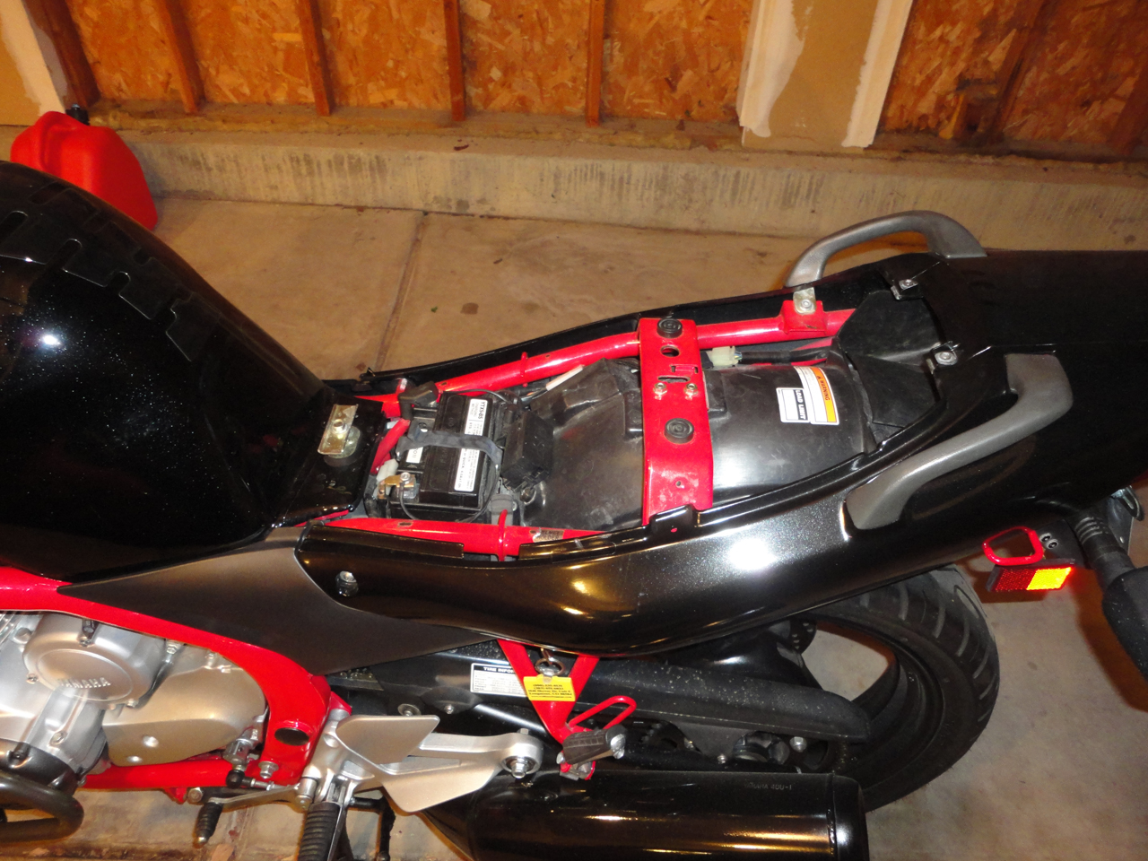
Remove seat:
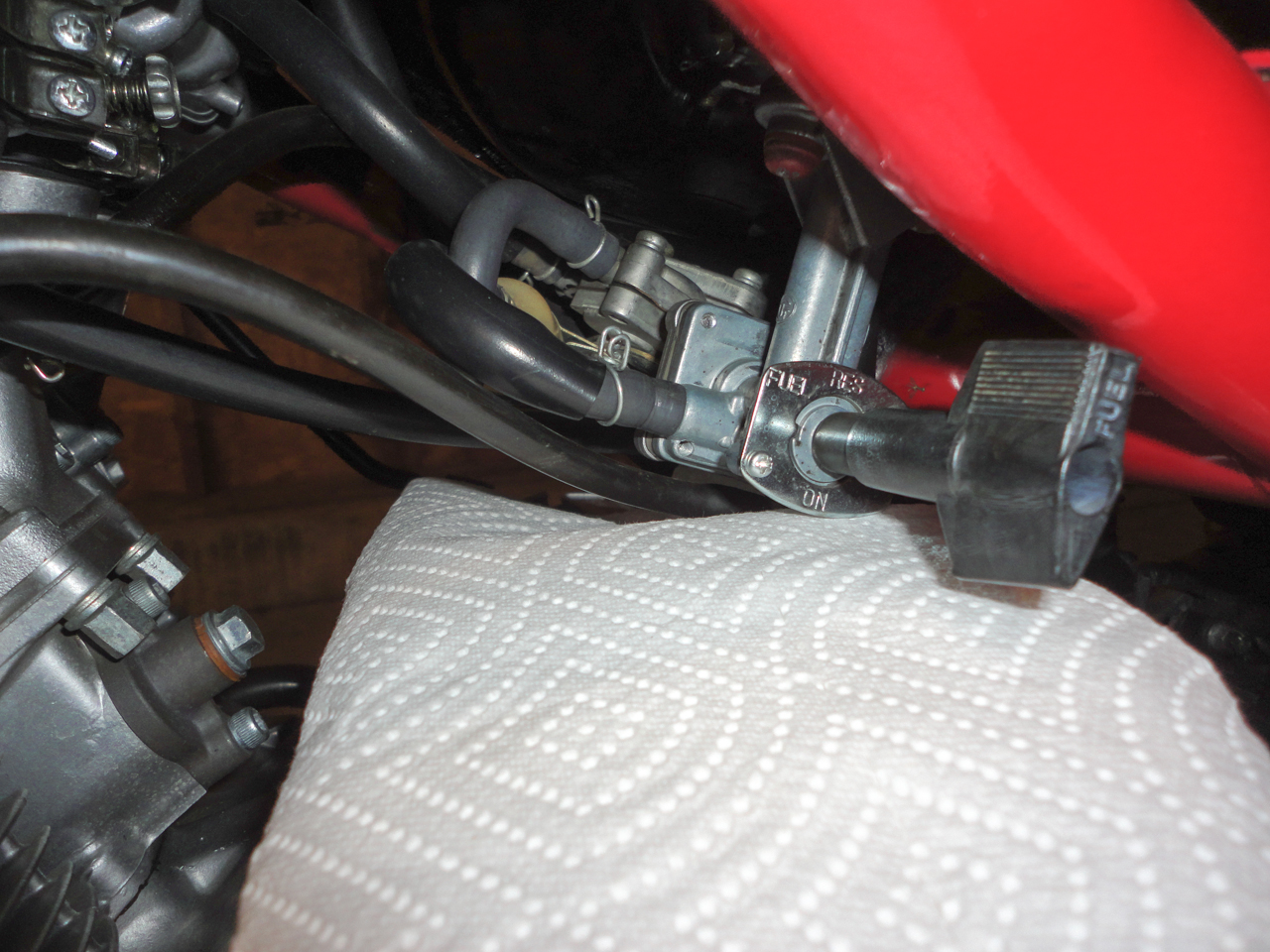
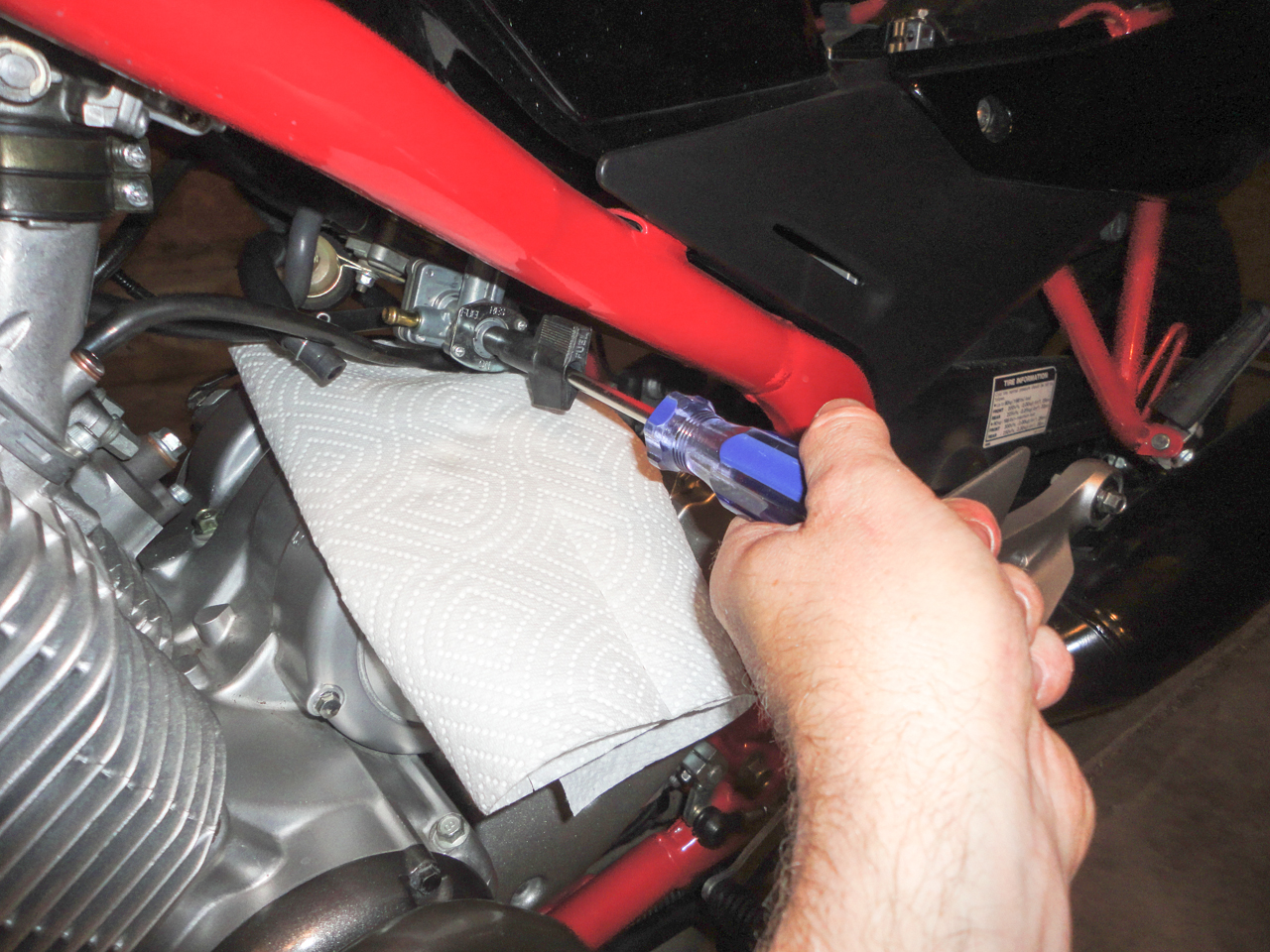
Place a rag under the fuel petcock and disconnect the fuel line:
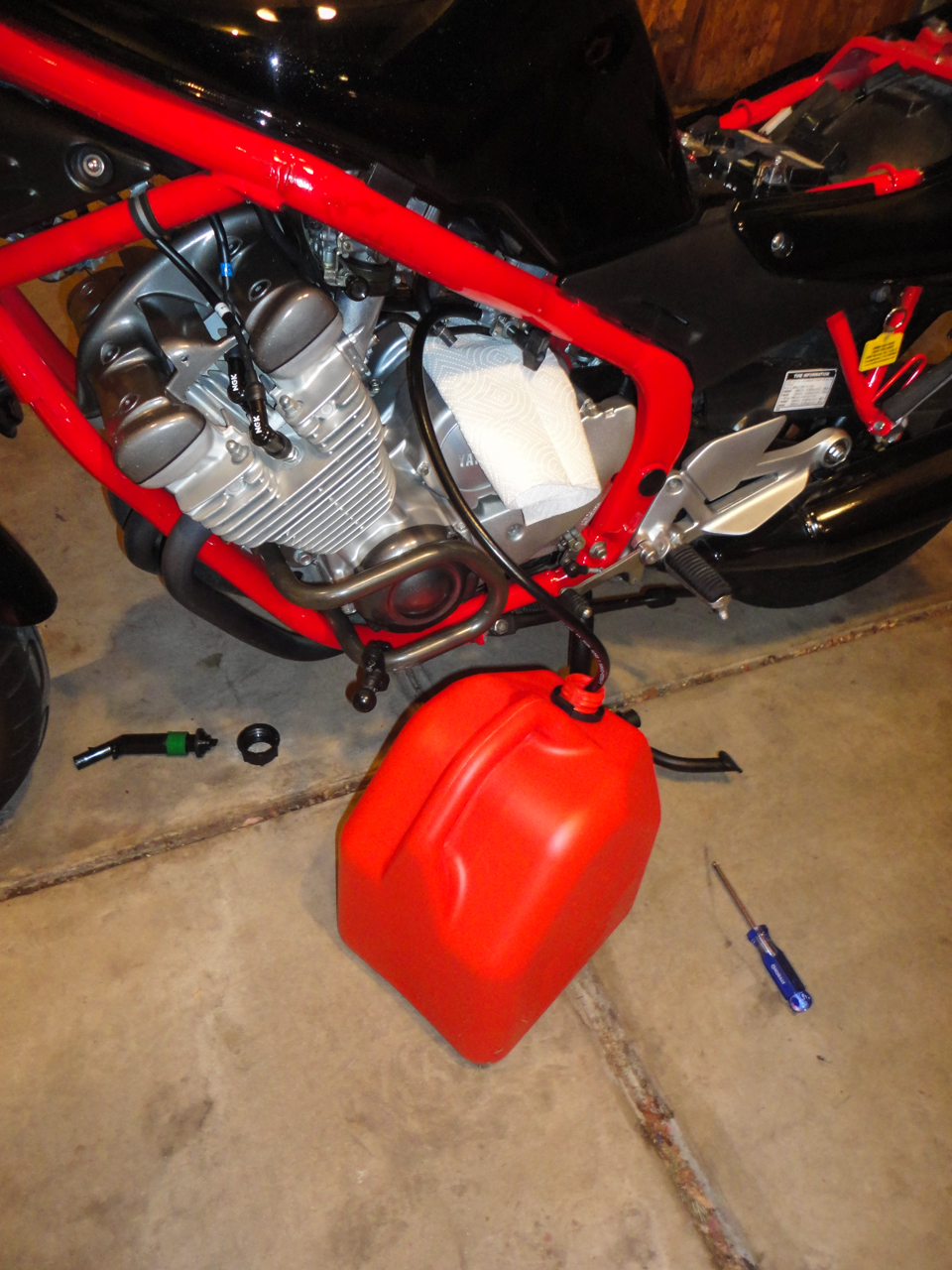
Connect a 3' length of 1/4" fuel hose to the outlet of the petcock. This will be used to drain the fuel tank:
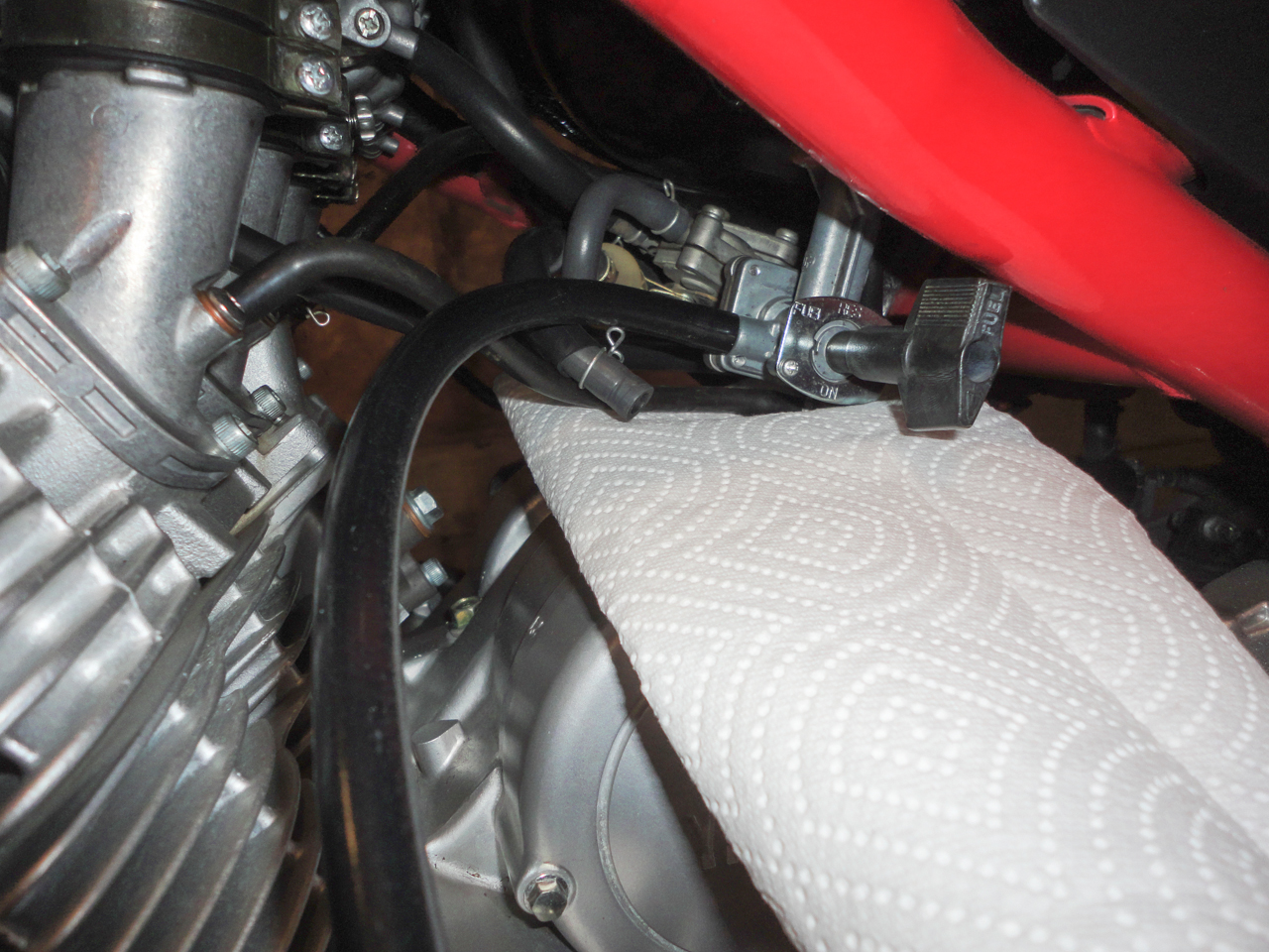
Place the other end of the hose into a 5-gallon fuel tank. Turn the petcock to the "prime" position. This will allow fuel to flow through the petcock and will drain the tank.
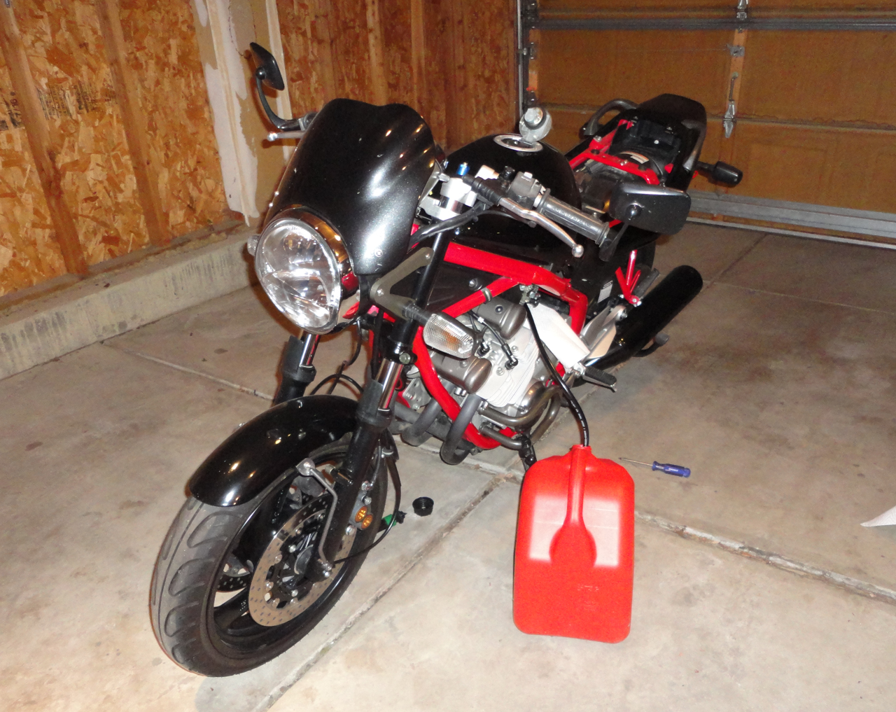
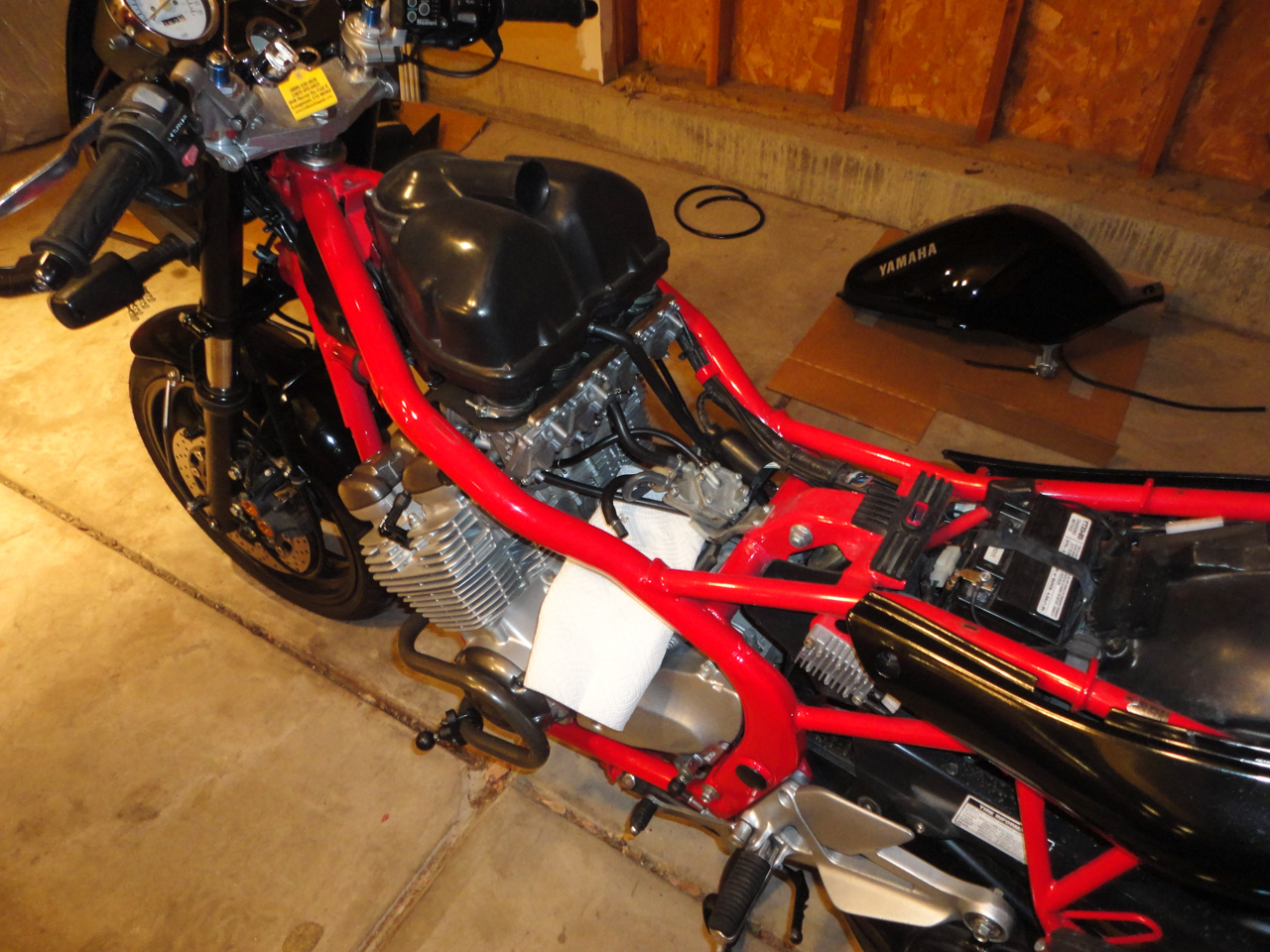
Carefully set the bike on its sidestand. This will allow the fuel to fully drain from the tank:
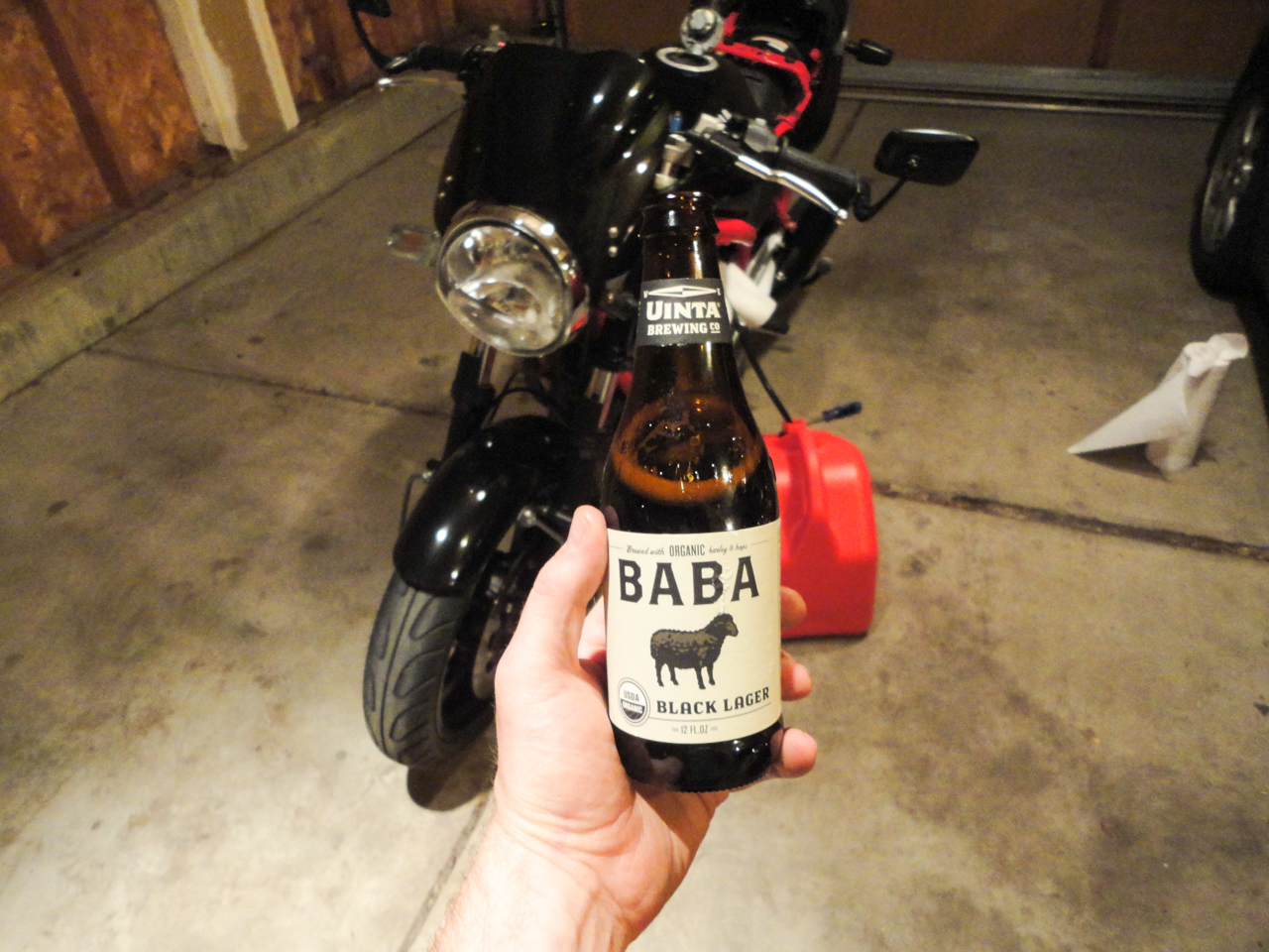
Grab a bottle of your favorite beverage and wait for the tank to drain:
When the fuel is fully drained, turn the petcock back to the "on" position. This will prevent any bit of remaining fuel from leaking out all over your bike as you remove the tank.
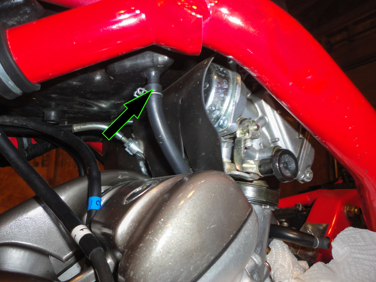
Disconnect the petcock vacuum line from the intake manifold:

Using a Phillips-head screwdriver, remove the screw securing the petcock handle to the petcock:
Using a 12mm socket and extension, remove the bolt securing the back of the tank to the frame:

Using a 10mm socket, remove the bolt securing the front of the tank to the frame (mine has been replaced with a socket-head cap screw for appearance):

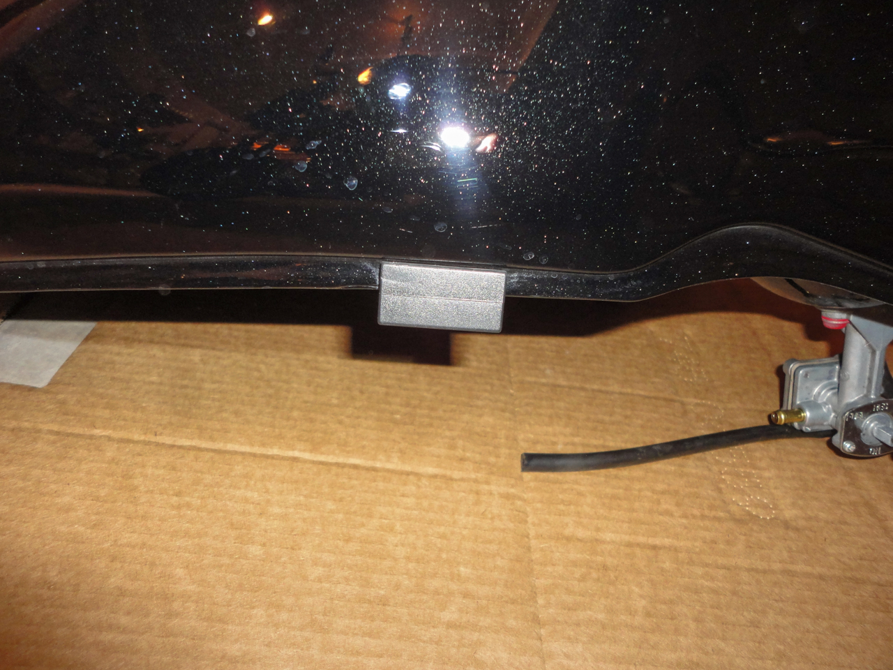
Carefully lift the tank upward and free from the bike. There is a drain hose attached to the underside of the tank which routes to the right-hand side behind the foot peg. When lifting, this hose may offer resistance but is not connected to anything; carefully pull the hose upward until the tank is free. Sit the tank off to the side and place it on cardboard to prevent damage:
When lifting the tank off of the bike and moving it, keep an eye on the tank insulator rubbers (located on the sides of each tank or near the rear mount). These have a tendency to fall off and get lost.
2. Remove the Airbox:
Using a Phillips-head screwdriver, loosen the screws securing the airbox to the carburetors (there are 4 screws total):
Using a 10mm socket, remove the bolt securing the airbox to the frame:
Using a pair of needle nose pliers, loosen the clamp and remove the crankcase breather hose:
Pinch the clamp and remove the hose from the bottom of the airbox:
Lift the airbox straight upward and remove from the bike. Sit on a piece of cardboard to protect from scratches.
3. Remove the Carburetors:
If your bike still has its carburetor bib, remove it and sit with aside with the airbox:
Using a 10mm wrench, loosen the throttle-cable locknut and remove the "pull" throttle cable.
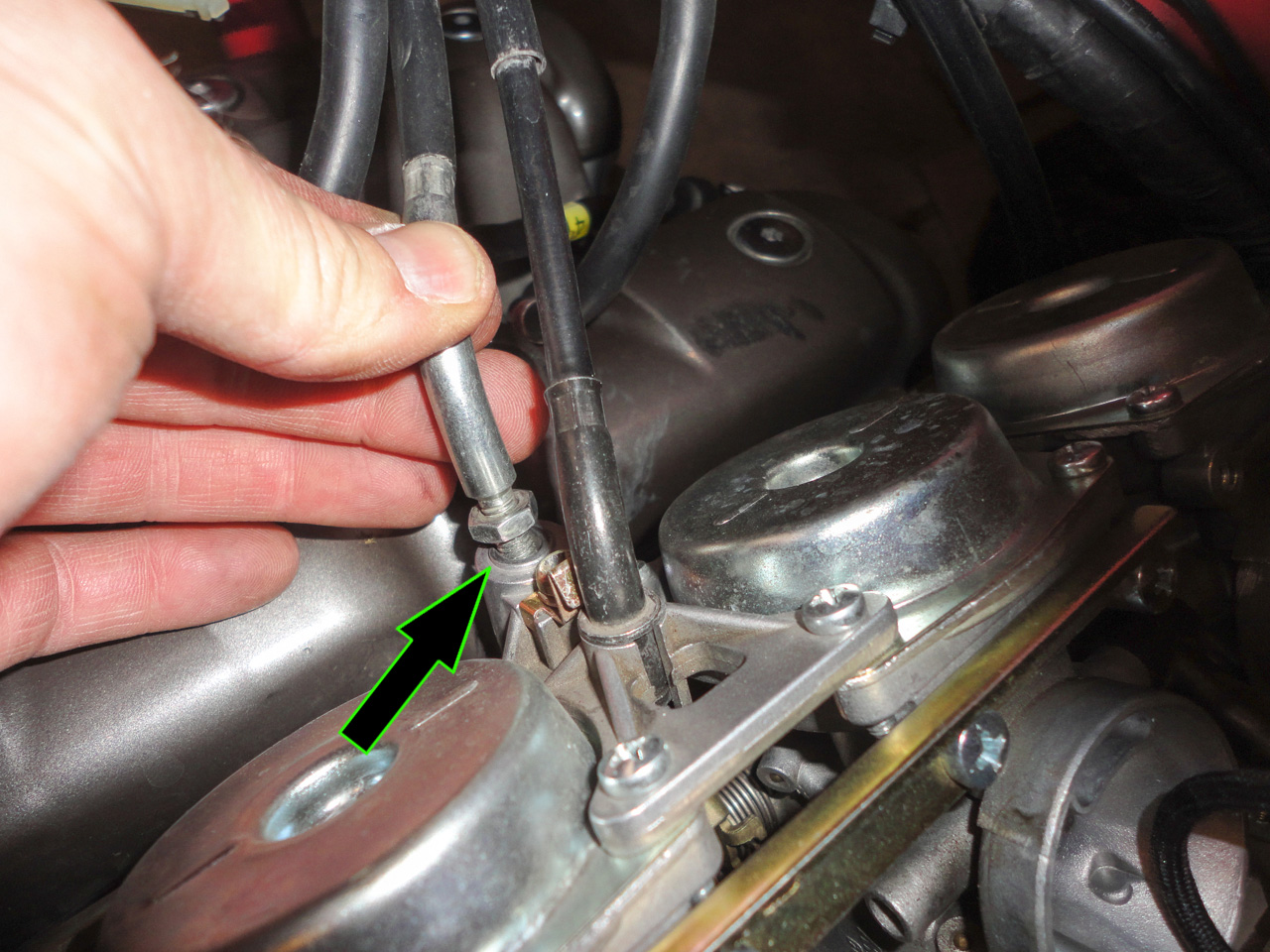
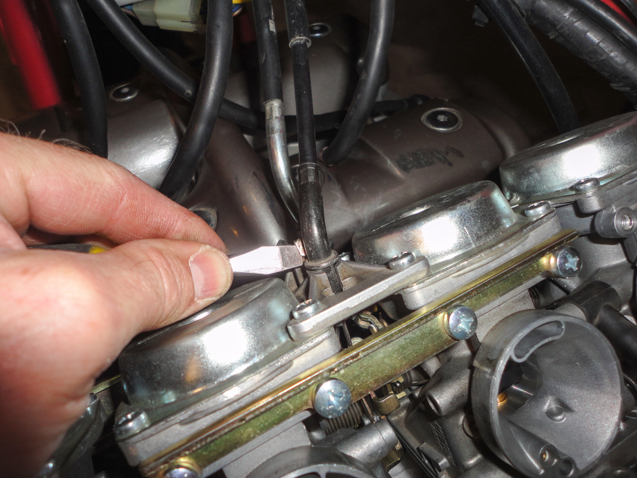
Using a flat-head screwdriver, press the securing tab and remove the "push" throttle cable.
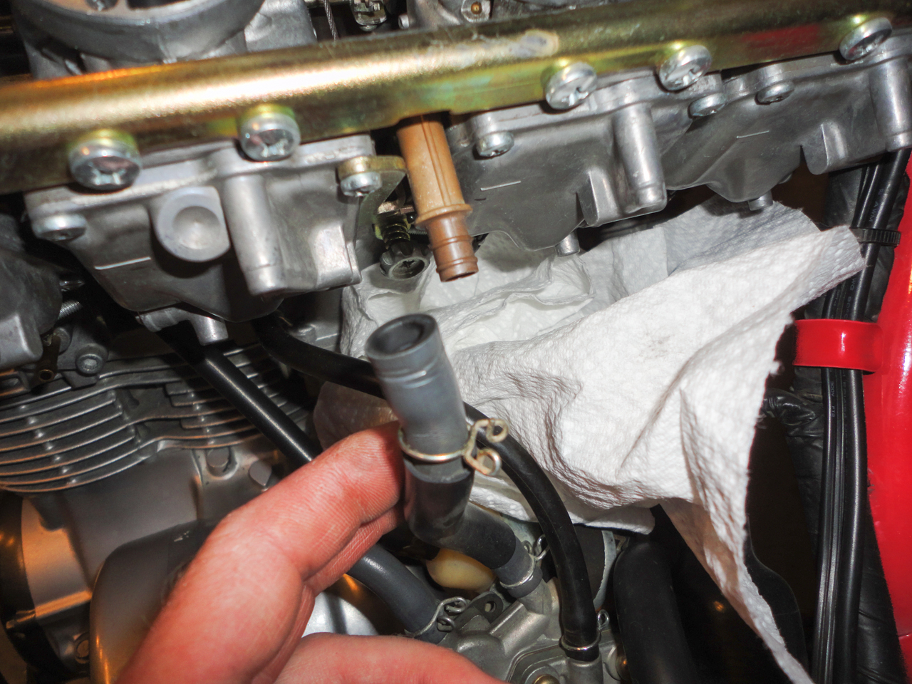
Using great care, press the tabs on the hose clamp and remove the fuel supply hose.
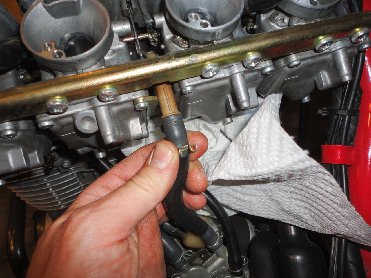
Note: The supply tee gets very brittle with age and can break if great care is not used. To remove the hose, remove the clamp and then gently rotate the hose until it spins freely on the tee. Then carefully wiggle it free from the tee.
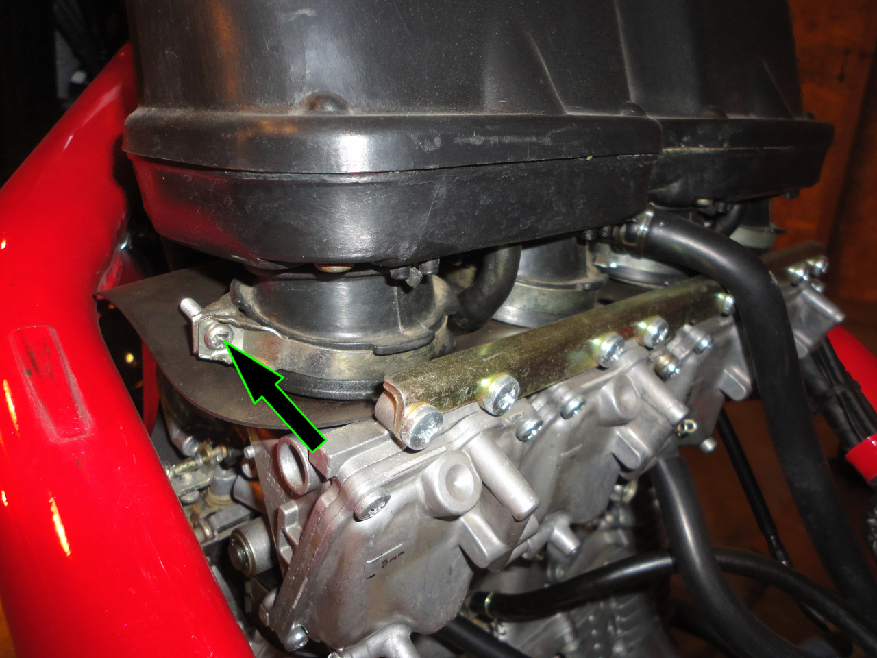
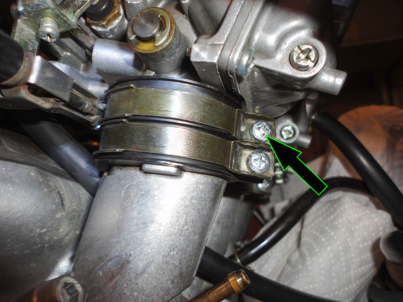
Using a Philips-head screwdriver, loosen the upper clamp securing each carburetor to the intake manifold (there are 4 screws total):
Grasp the carburetor assembly on each side and pull upward. Wiggle the carburetor assembly front-to-back while pulling upward. It will slowly wiggle free from the intake boots.
Drain the fuel from the carburetor assembly and sit aside. Place the carburetor assembly in a plastic bag to protect it from dirt and debris.
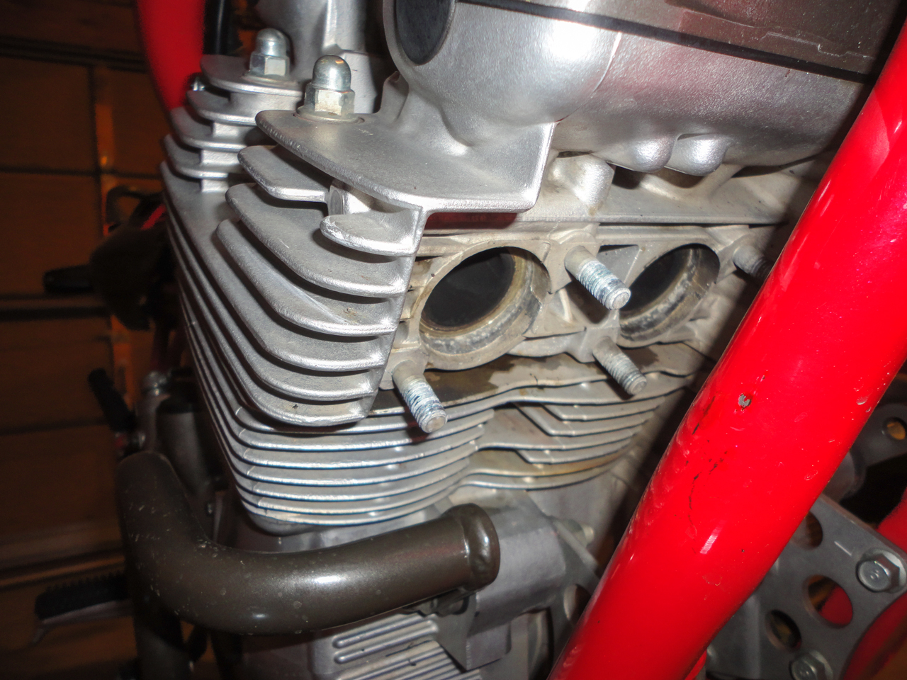
4. Remove the Intake Manifolds:
Disconnect the vacuum hoses from the first two intake manifolds (if you didn't remove them when removing the tank) and set aside:
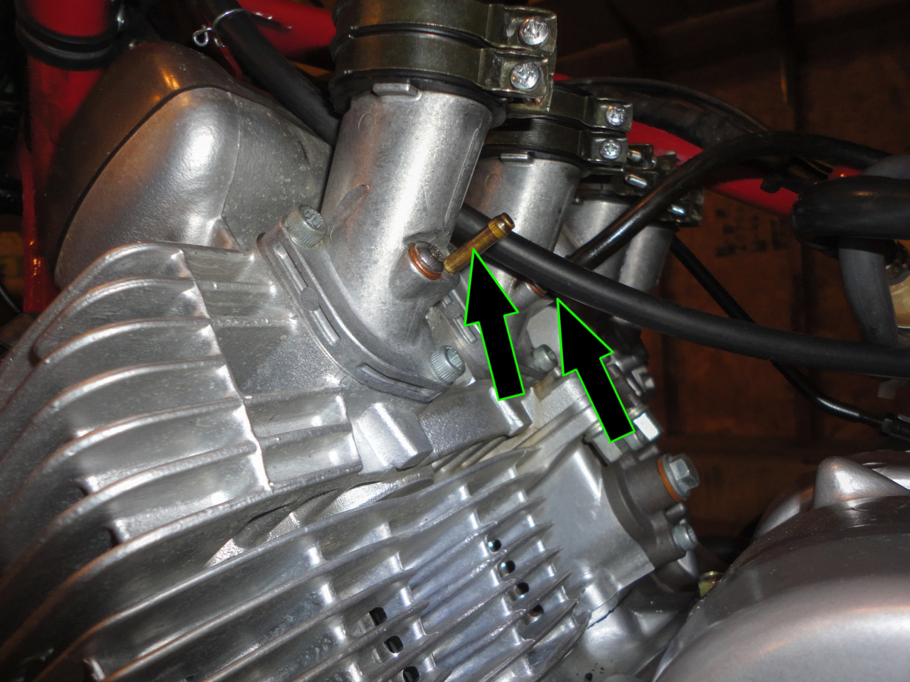
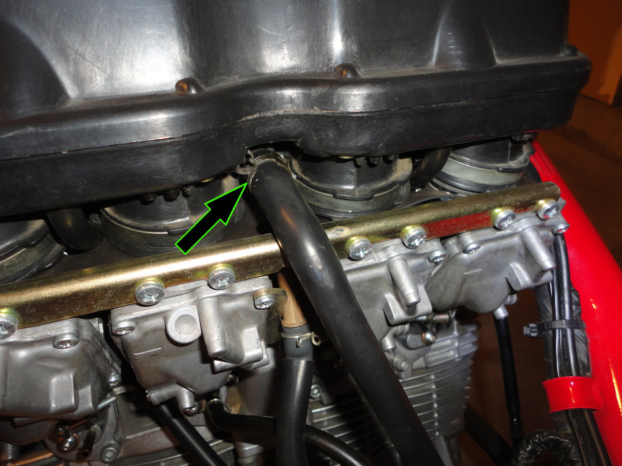
Using a 5-mm hex-head socket (Allen-head socket) and extension, remove the bolts securing the intake manifold to the cylinder head:
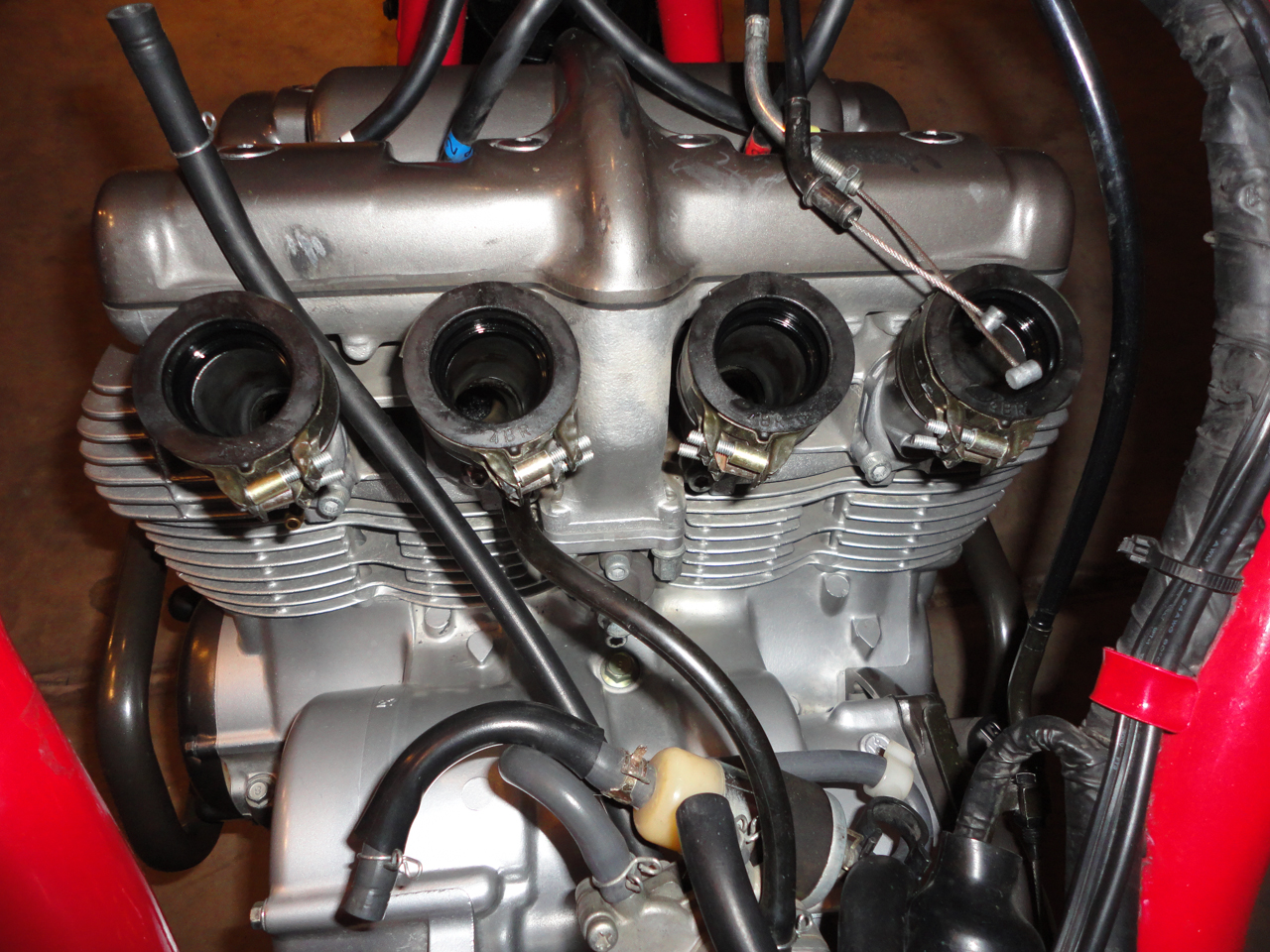
Remove the four intake manifolds and sit aside. If the manifolds are stuck in place, loosen them by tapping them (lightly) with a rubber mallet:
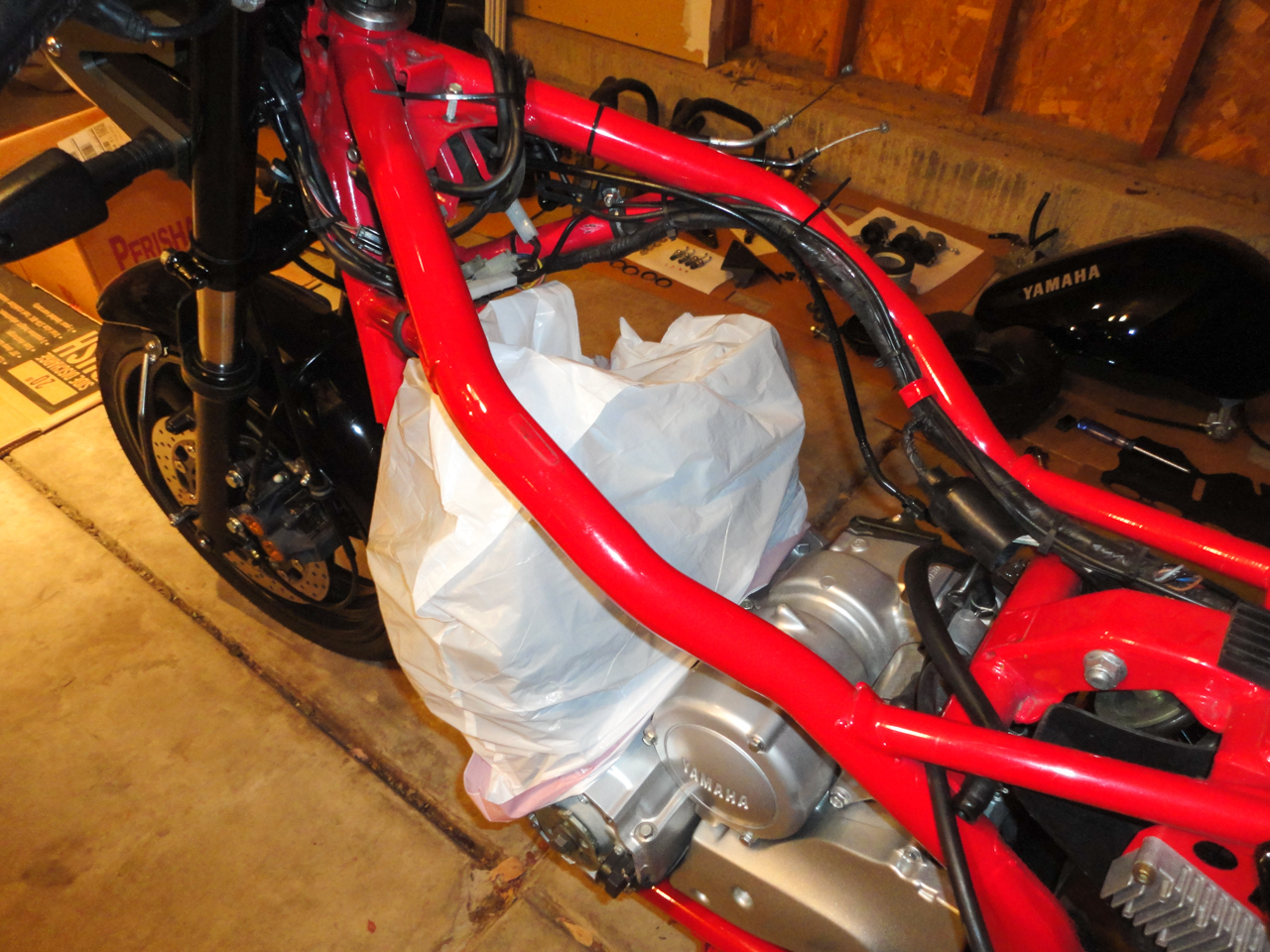
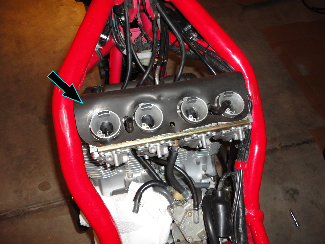
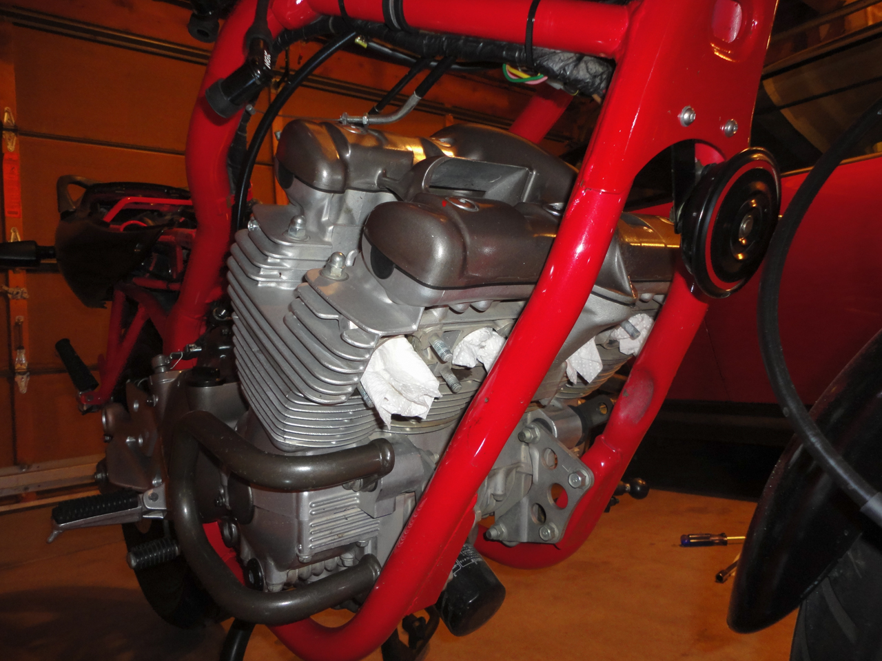
Place a piece of paper towel into each of the inlet holes in the cylinder head to prevent debris falling into them:

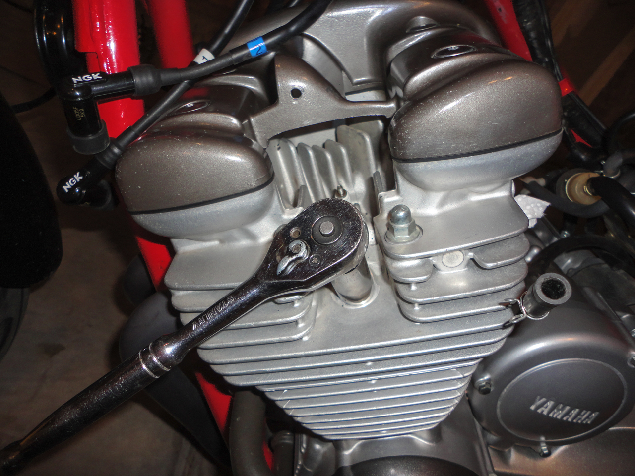
5. Remove the spark plugs:
Make sure each plug wire is labeled as to the cylinder it serves. Grasp the spark plug resistor cap and pull upward while turning, to remove:
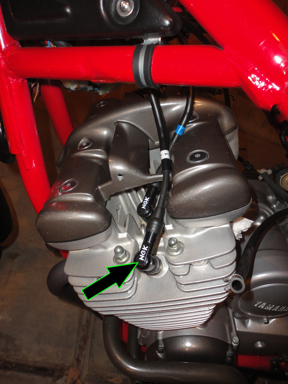
Using a 5/8" spark-plug socket, remove each spark plug:
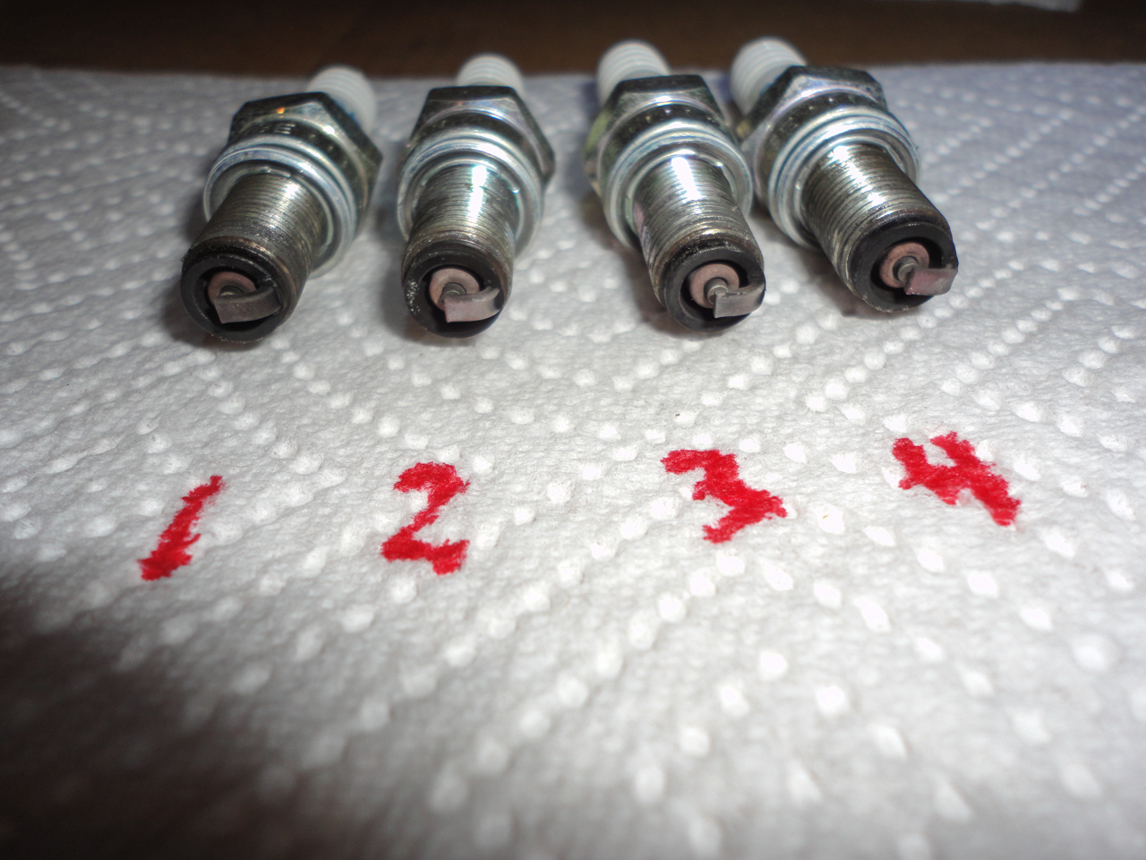
Label a piece of paper and place the spark plugs according to the cylinder they were removed from. Note their condition. This will be handy later when tuning. Note that in the spark plugs pictured, below, that #1 seems to be slightly rich, #2 & #3 seem to be slightly lean and #4 seems to be right-on:
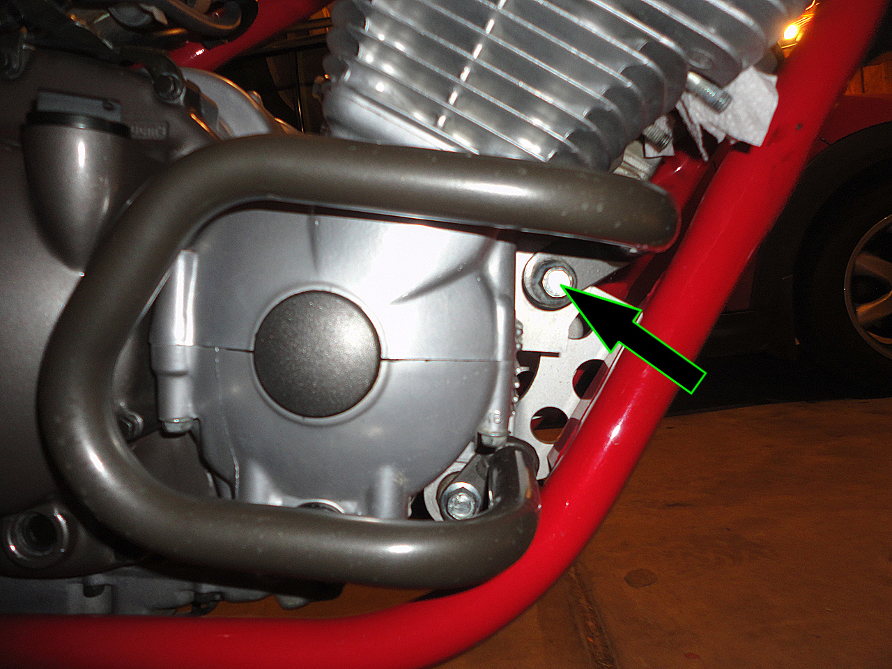
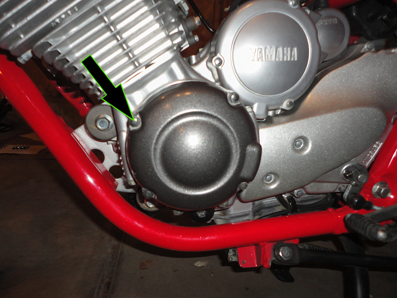
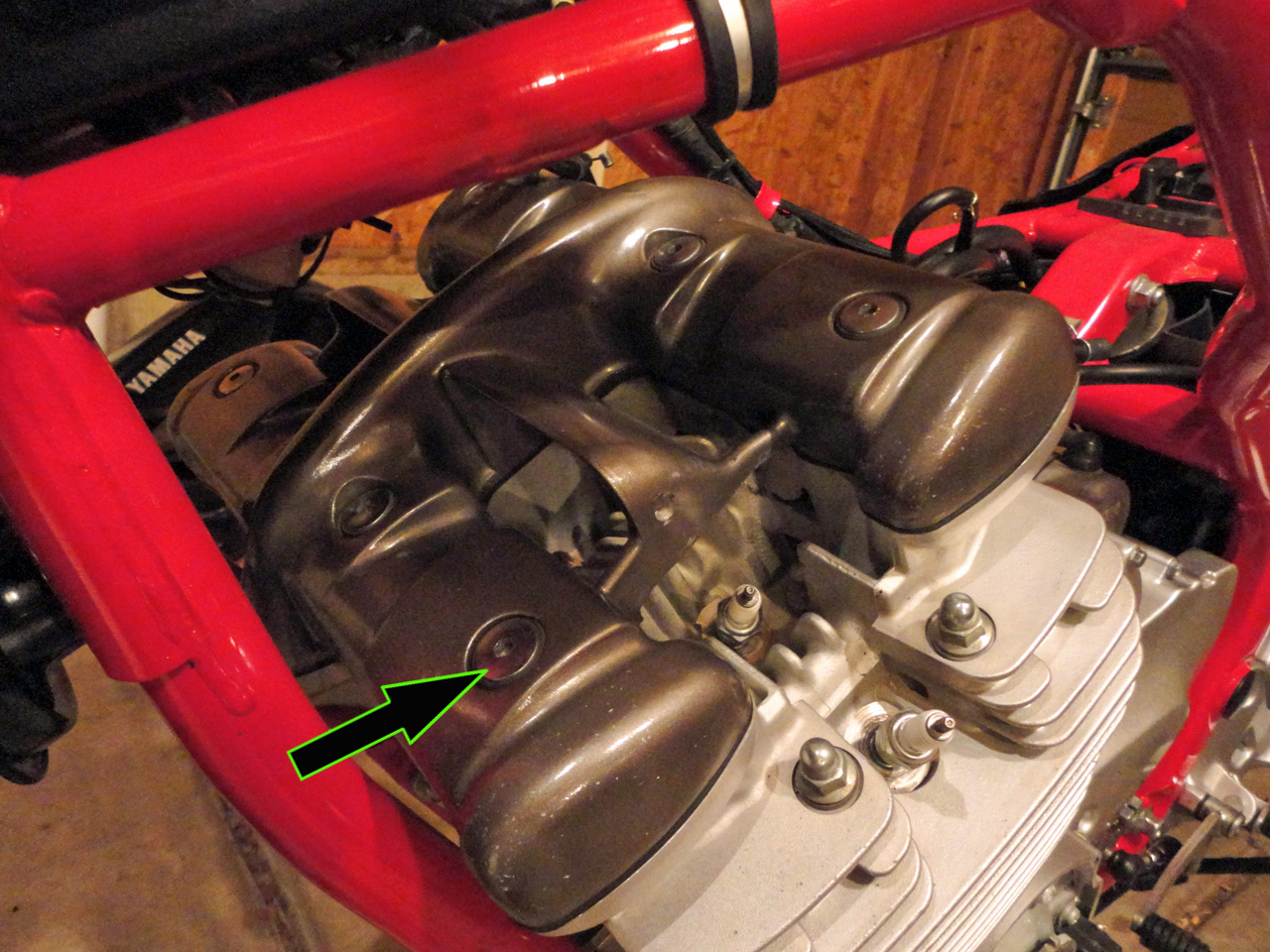
6. Remove the Exhaust:
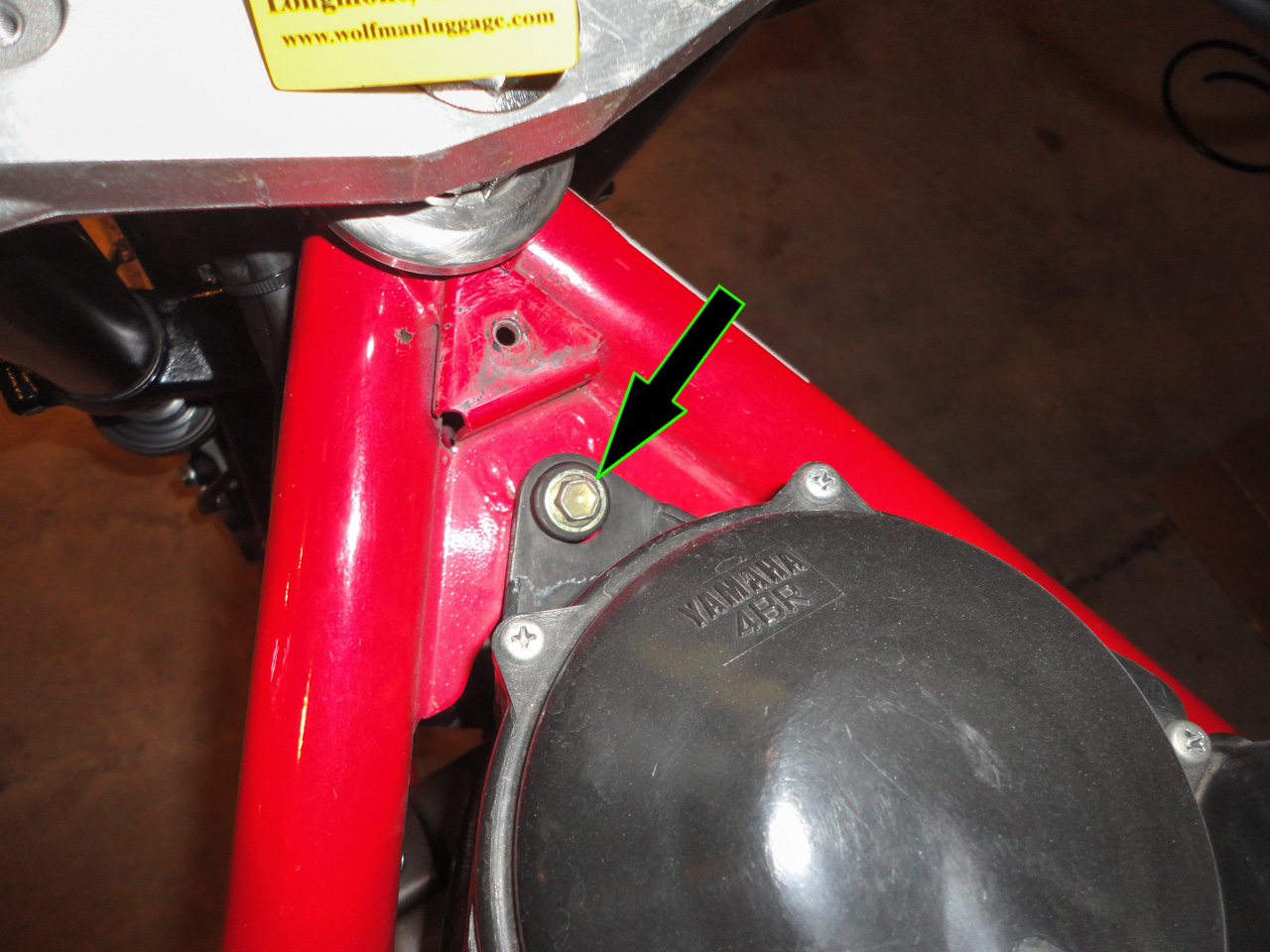
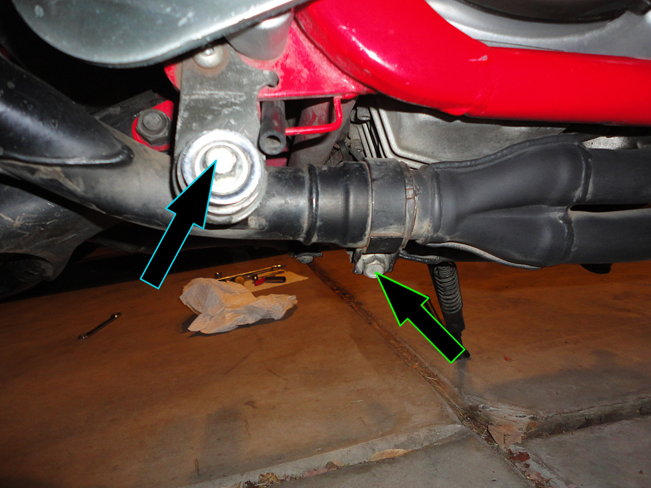
Using a 10mm socket, loosen the bolt securing the exhaust clamp (green arrow). Using a 14mm socket, remove the bolt securing the muffler to its front support bracket (blue arrow):
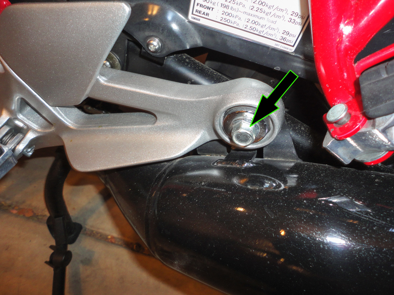
Using a 14mm socket and 14mm box-end wrench, remove the bolt & nut holding the muffler to the rearset:
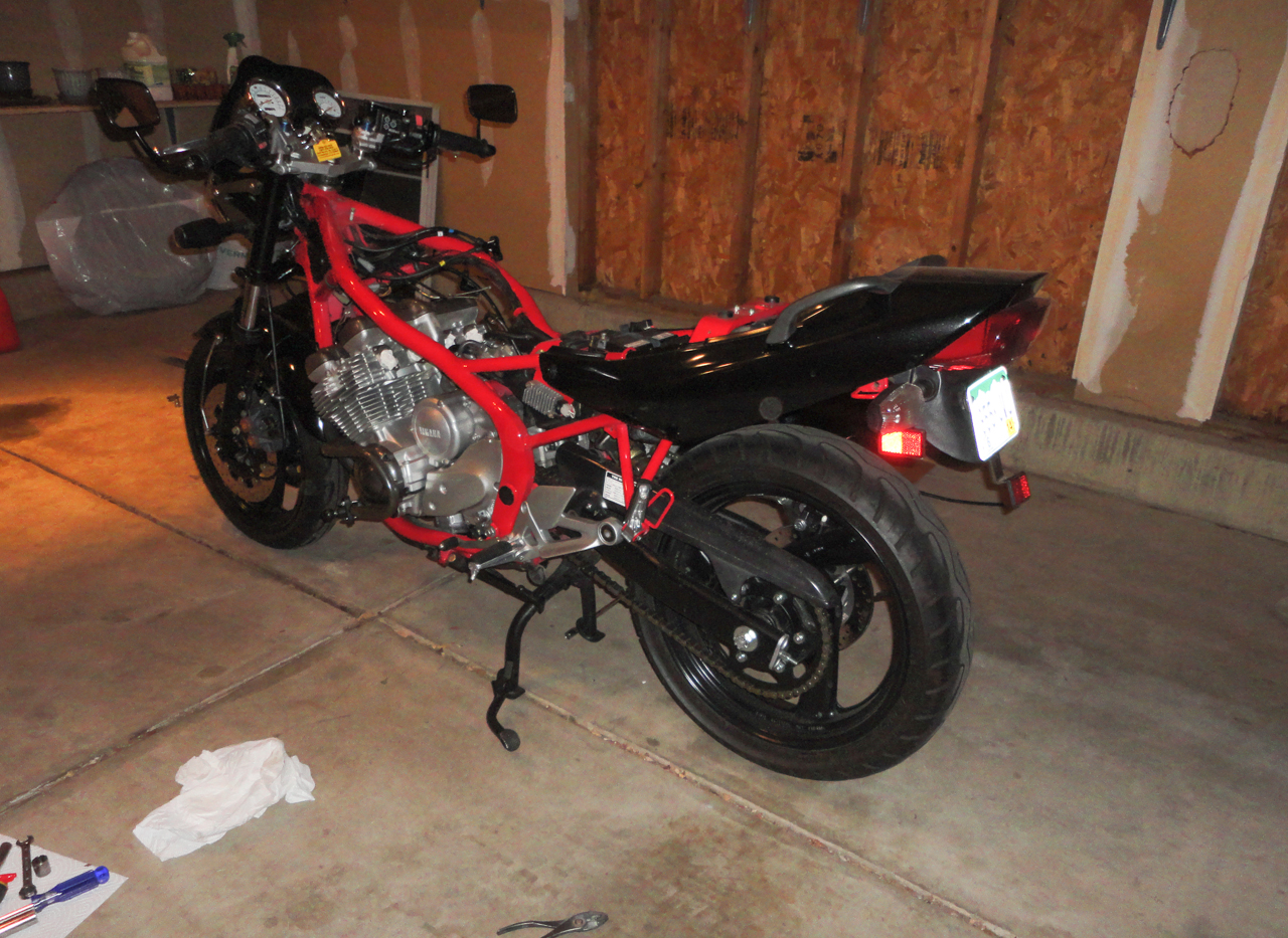
Rotate the muffler downward, pushing it toward the wheel as you do so that the bracket clears the rearset. After rotating the muffler, pull it free from the header and sit aside:
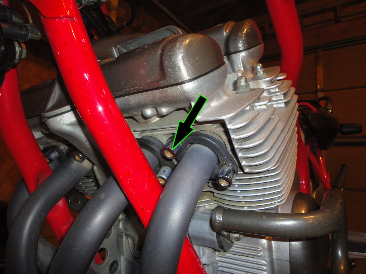
Using an 8mm hex-head (Allen-head) socket and an extension, remove the bolts securing the exhaust header to the cylinder head (there are 8 bolts in total):
Pull the exhaust header toward the front wheel to clear the frame and sit aside:
Stuff a piece of paper towel into each exhaust port to prevent debris from falling into them:
6b: Remove Engine Guards (if equipped):
Using a 14mm socket and 14mm wrench, remove the bolts attaching the frame guard to the engine. Note: These bolts are also the engine mount bolts. Remove each bolt, one at a time, slide the guard out of the way and put the bolt back in before moving onto the next. OR, support the engine while removing:
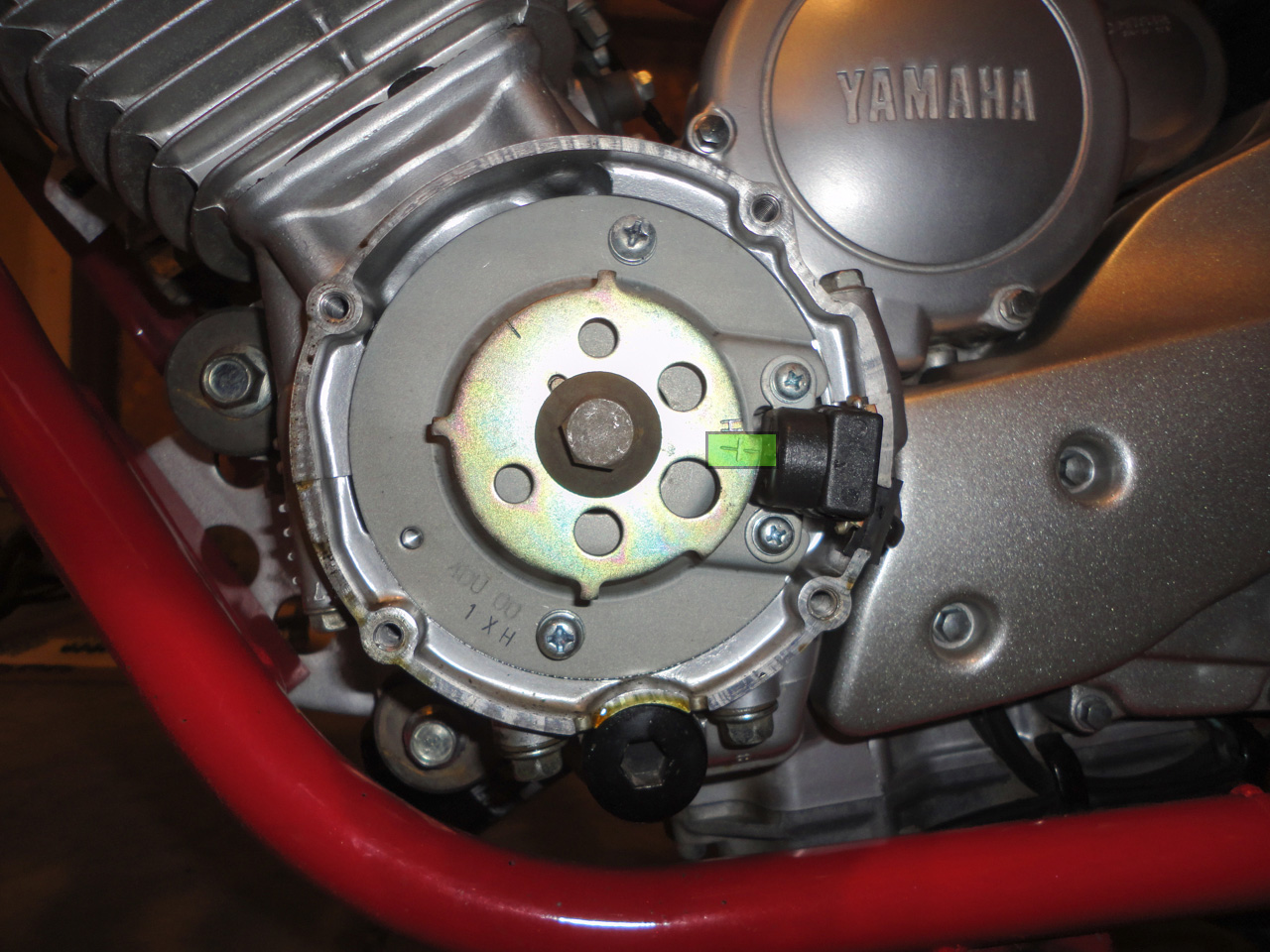
7: Remove side cover and set to top-dead-center (TDC):
Using an 8mm socket, remove the four bolts securing the side cover in place. Remove the side cover and sit aside:
Using a 14mm wrench, rotate the engine counter-clockwise until the "T" mark on the rotor aligns with the mark on the pickup sensor:
8: Remove the valve cover:
Using a 4mm hex-head (Allen head) socket, remove the 8 bolts securing the valve cover to the cylinder head. Note: Remove these bolts in a criss-cross pattern, 1/4 turn at a time, to prevent damage to the valve cover.
There are small rubber grommets between the valvecover bolts and the valve cover. Pull these out and keep them with the bolts to prevent them from being lost. They are expensive; $9 each.

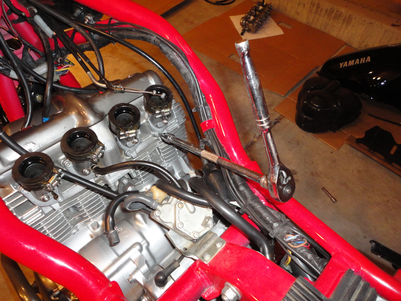
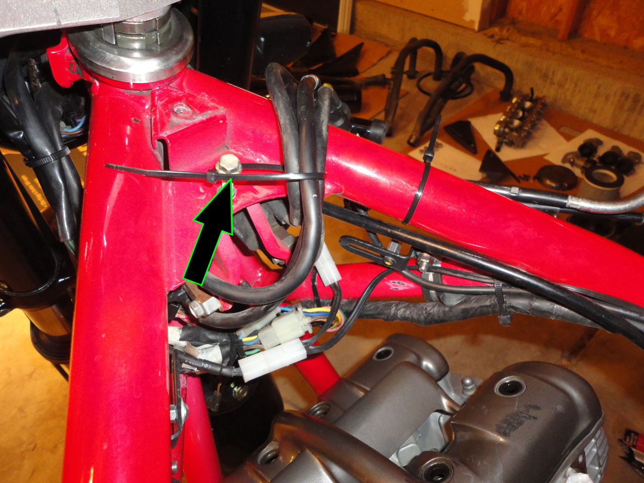
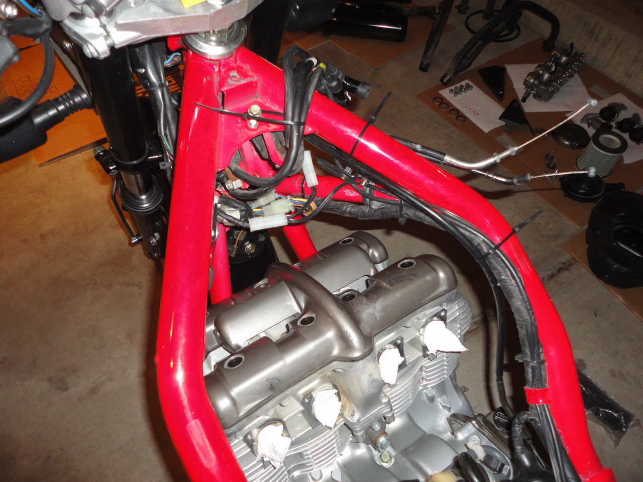
In preparation for removing the head, use zip-ties to secure the throttle cable and spark plug wires well out of the way:
Lift the valve cover off of the cylinder head and place in a plastic bag to keep clean. Sit it aside. Note: If the VC does not want to come loose, gently tap on it using a rubber mallet to break the seal of the gasket.
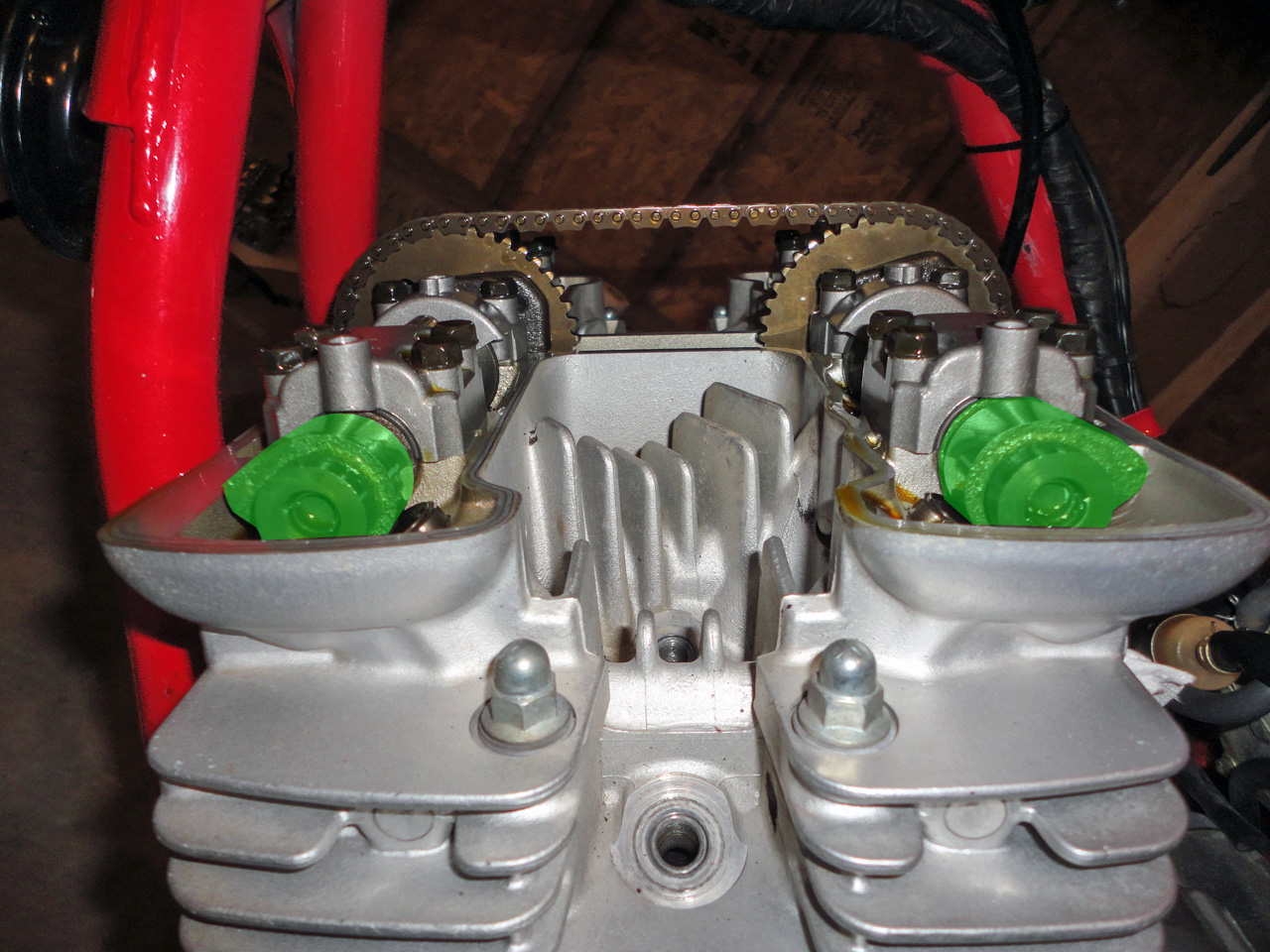
9. Remove the camshafts:
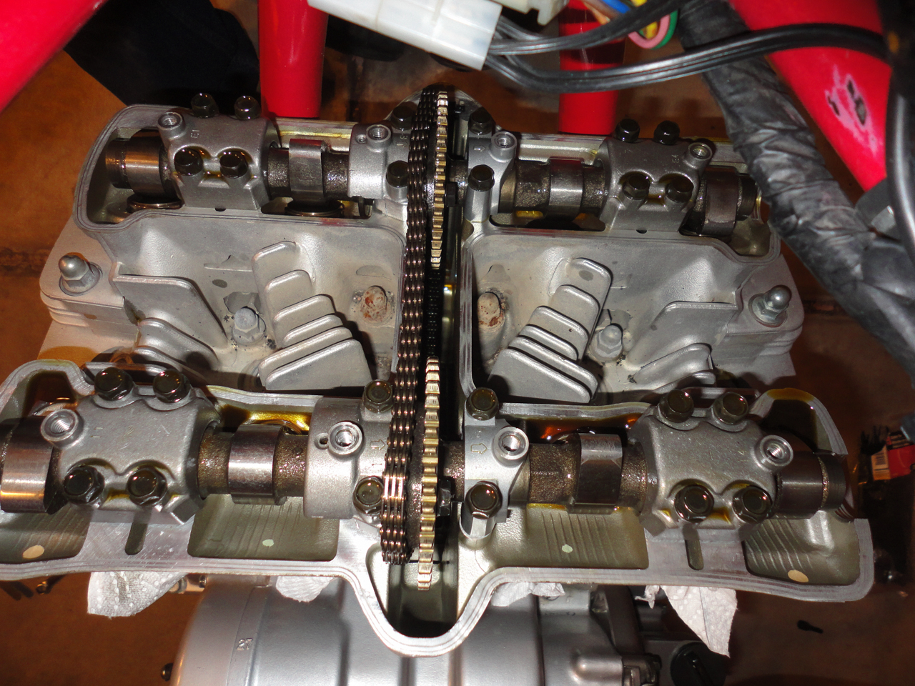
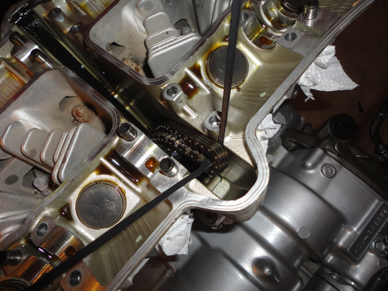
With the valve cover removed, you will have access to the valvetrain. In preparation for removing the cams, the engine was placed at TDC for the #1 cylinder. To verify the #1 cylinder is at TDC, confirm that the cam lobes for the #1 cylinder point away from each other as shown:
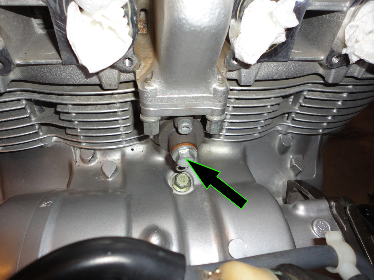
Using a 14mm socket, remove the bolt securing the timing tensioner adjustment spring:
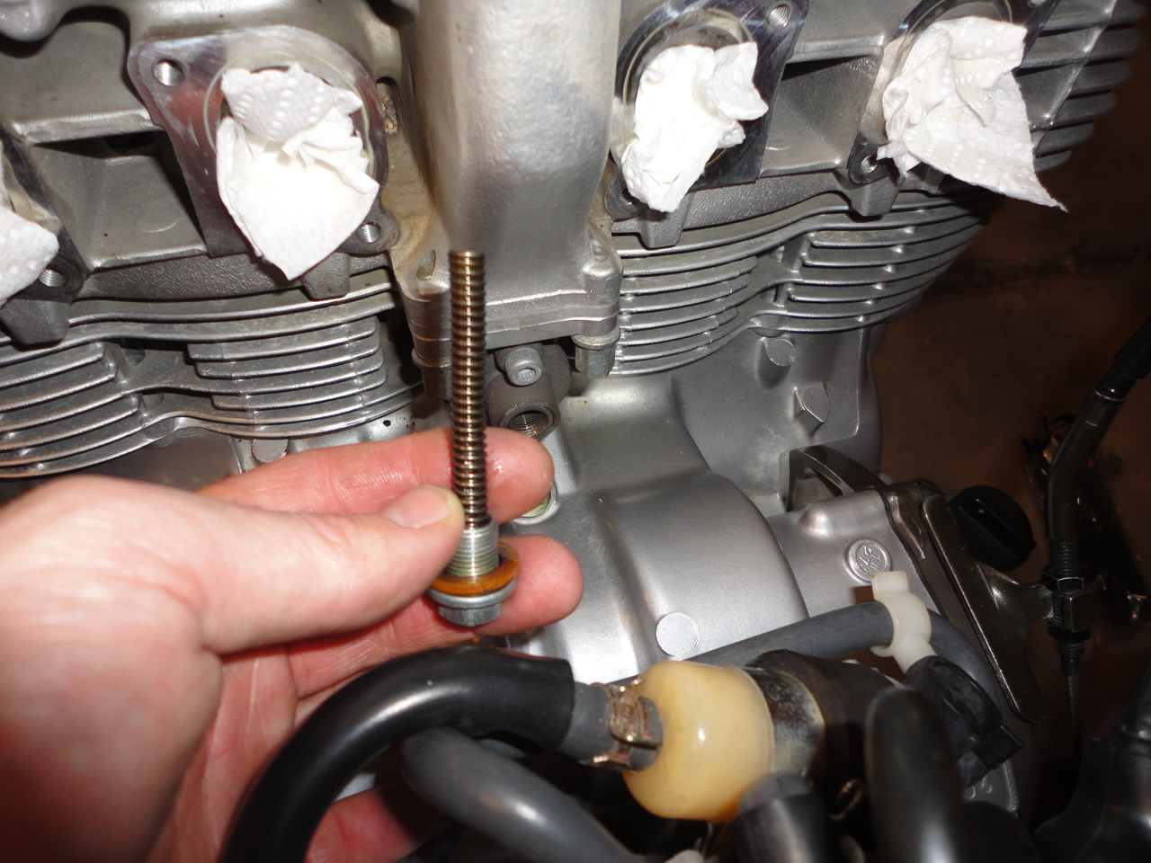
Behind the bolt, you will find a copper washer and two springs. Ensure both springs came out and place them in a ziplock bag:
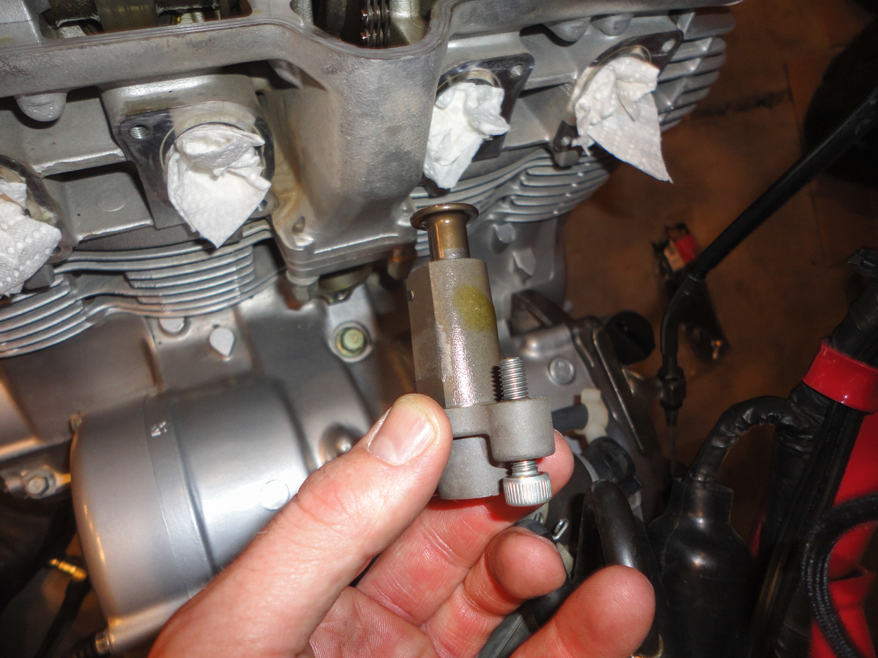
Using a 5mm hex-head (Allen head) socket, remove the two bolts securing the timing tensioner to the engine. Withdraw the timing tensioner and note its orientation:
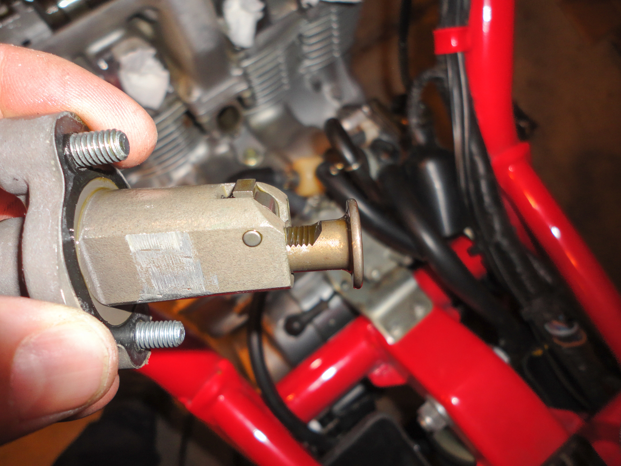
Stuff a piece of paper towel into the tensioner hole to prevent debris getting into the engine:
The timing chain should now be loose enough that you can lift it off of the cam gears. Lift it upward and sit it aside:
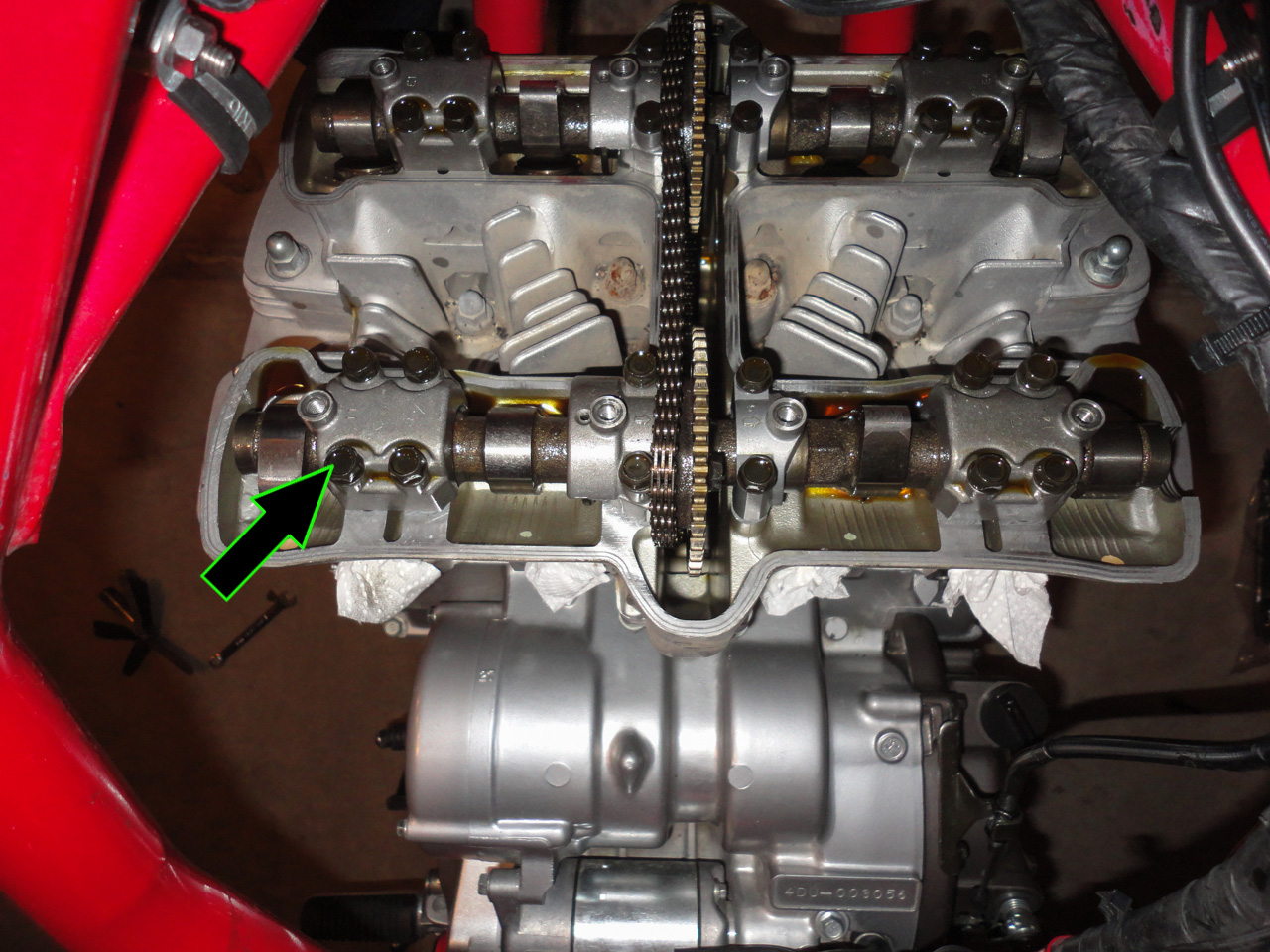
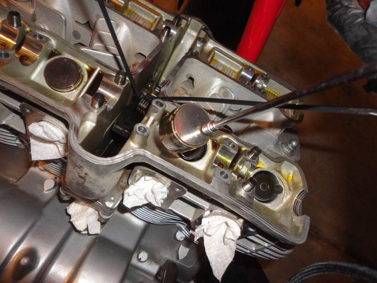
Using a 10mm socket, remove the 12 bolts securing the cam caps. Note: Remove these bolts in a criss-cross manner, a 1/4 turn at a time. This will prevent damage to the camshaft. Continue until all bolts are loose and then remove the cam caps and lift out the cam. Note the location that each cam cap and cam go and mark them with a sharpie so that they can be installed in the same location
To prevent the timing chain from falling into the engine, secure it with a pair of zip ties. This way, if it does fall in, it'll be easily removed:
Using a magnetic pickup tool, remove each lifter and place it into a labeled bag noting where it came from. I label my with the location and cylinder number. For example, if I remove the lifter from the #3 intake valve, I'll label it I3.
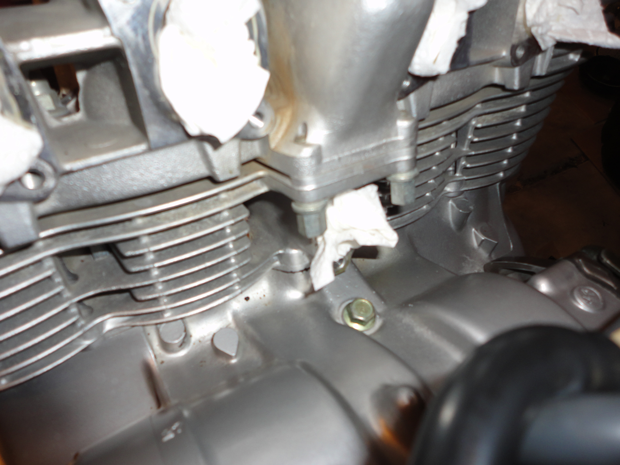
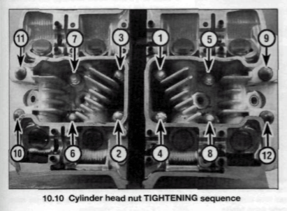
With all of the lifters out, it's time to remove the cylinder head. Loosen the cylinder head bolts in order, 1/2 turn at a time, until all bolts are loose, and then lift the cylinder head off. Note, this photo shows the tightening sequence; remove in reverse of order shown:
Lift the cylinder head from the bike, place in a plastic bag and sit aside.
To prevent any debris from getting into the engine with the cylinder head removed, cover the cylinder with a trash bag anytime you are not working on it: