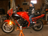
O.K., here goes. Just an fyi, I had pulled the tank and fairings to clean the carbs and do a little wiring at the rear tail light. This made the installation below super easy to do as everything was opened up.
I installed heated grips last year, but never wired them in. I wanted it done before this riding season, otherwise I knew it wouldn't get done again. I'm also waiting for a USB power adapter to arrive and I might add some small fog/driving lights, at some point down the road, if there's enough power available. Either way, I wanted a nice clean install, easy to add to and easy to check up on.
The following is what worked best for me.
What I Used:
1. Fuse Block, in my case a 30 amp LED ATO fuse block
2. Grounding Block, a.k.a. Terminal Block
3. 1 inline ATO fuse holder
4. 30/40 amp Relay with harness and socket
5. multi-colours of primary wire
First up, I spent a bunch of time deciding where I wanted to mount everything and run the wires. I wanted it to look clean and somewhat hidden, at least for the power runs. My Fuse block was about 1"- 1 1/4" high. It was the smallest 4 fuse block I could find that included a cover and was local. I didn't want to wait since I had everything else at the house. I wanted this mounted under the seat in case of a blown fuse, I'd have easy access. I basically placed it all over, held it with duct tape and put the seat on to see if it would fit. This was really the only place it would work without shaving down the seat, but it definitely works for me. The relay and harness mounted nicely under the seat cross-member, same side as the fuse block.


Next, I wanted as easy an install as possible. To me this meant if I could avoid hacking in to the stock wiring harness then I would. I'm not afraid to cut, splice or solder. I actually do quite a bit of it, but if I didn't have to, I wouldn't...and I didn't as you shall see.
Main power (pin 30) and ground (pin 85) of the relay, I simply hooked to the battery posts. I soldered an inline fuse to the power wire. Now I needed to find a good source for switched power as I wanted this block on only when the ignition was on. I knew that i could tap into any number of wires but again, i was trying to avoid that. I decided to have a look at the factory fuse box, especially since it's sitting right beside my new one. I like short wire runs ;) . Well, as luck would have it, I flipped the stock box over and noticed that the power "out" from the fuses was jumpered across all three, ignition, headlight and turn signal. Nice! I crimped on a terminal connector and plugged it in...

...et voila! Switched power to the relay (pin 86)
Now I needed to find a good location for my grounding block. I knew I wanted it up front since that's where the 3 accessories that I was thinking about would be located. I had an idea, but wasn't sure if my grounding block would actually fit or if I'd be able to mount it solidly. Well, it did, and I won't keep you in suspense any longer. Many of our European fellow xj'ers have bikes that come with an oil cooler rad. It mounts below the lower triple. I believe we all have the mounting plate and holes for it though. At least my '96 did.
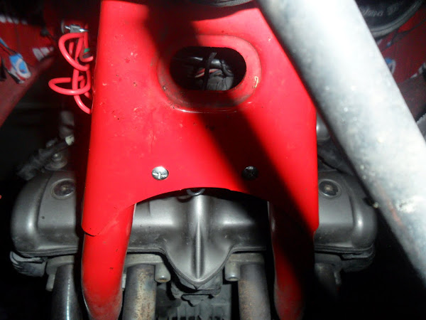
From the terminal block, I ran a short wire ( :thumbsup: ) along the frame to the horn mounting bolt for my main grounding source. Loosend the nut, held wire against stud, tightened nut...just that easy ;) . I sealed it all up with a little liquid electrical tape.

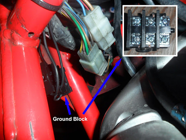
O.K., what's left...right, accessory power from the fuse box (which is actually powered by the relay (pin 87/87a)). I roughly pulled some primary wire along the route I wanted to take, added female spades to one end and bullet connectors to the other. I ended up just running two lines up to the front for now. I taped the two wires together to form there own loom and followed the factory harness up the right side of the bike. I hooked one wire up to the heated grips and the second I tie wrapped to the frame, until my usb port arrives. You can see the bundle in the pic above that shows the mounting bolts for the ground block.
Here's a quick pic showing the layout of all the wire runs.

...and here's a final labelled pic of everything tucked away nice-n-tidy like.

Hope someone finds this helpful...